Ultrasonic Welding Mold for Electronics: How to Specify Precision Welding Tooling
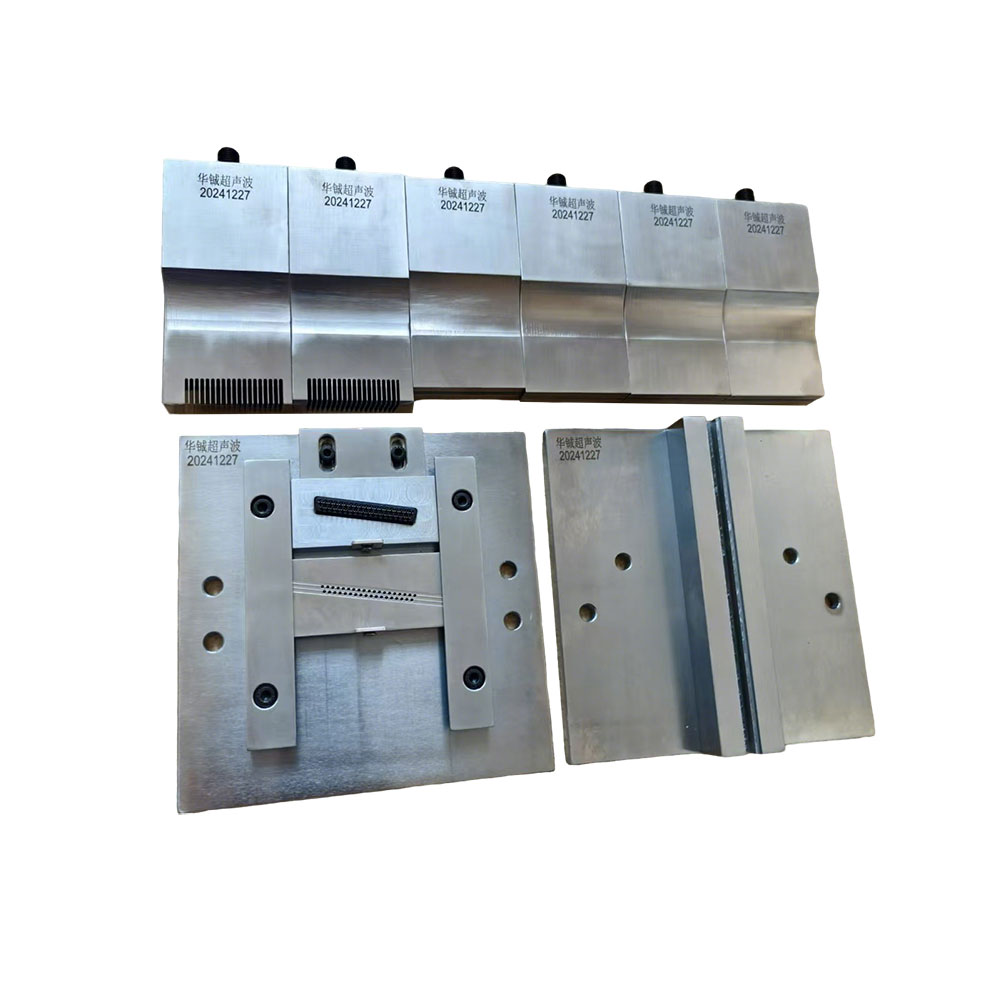
An Ultrasonic Welding Mold for Electronics is a precision tooling component that directly determines how ultrasonic energy is transferred into an electronic plastic assembly. In applications such as sensor housings, connector components, cable assemblies, battery-related plastic parts, switches, small enclosures, and other electronic components, the welding mold must achieve repeatable energy transmission without damaging sensitive internal structures. The challenge is not simply to make a mold that fits the plastic part. The tooling must match the ultrasonic frequency, joint geometry, material characteristics, amplitude distribution, pressure conditions, and production cycle.
For electronics manufacturers, these requirements become more demanding as components become smaller, wall thicknesses decrease, and dimensional tolerances become tighter. A well-designed Ultrasonic Welding Mold for Electronics should provide stable positioning, controlled vibration transmission, consistent weld formation, and sufficient durability for repeated production. Mold design therefore needs to be treated as part of the ultrasonic welding system rather than as an isolated accessory.
How an Ultrasonic Welding Mold Works
Ultrasonic plastic welding typically converts high-frequency electrical energy into mechanical vibration through an ultrasonic transducer and converter. The horn then transfers this vibration to the workpiece, while the fixture or lower mold supports and positions the component.
The mold has two fundamental functions: accurately locating the workpiece and providing an appropriate reaction surface during welding. If the component moves during ultrasonic vibration, the welding interface may not receive uniform energy. This can produce incomplete welding, flash, inconsistent joint strength, or dimensional deformation.
For electronics, positioning accuracy is particularly important because many plastic housings contain cavities, terminals, wires, circuit boards, clips, inserts, or other components that cannot tolerate excessive mechanical loading.
The mold must therefore support the part at structurally appropriate locations while avoiding unnecessary contact with sensitive features.
Frequency Must Match the Welding System
Ultrasonic welding equipment commonly operates at different frequencies, and tooling must be designed for the specific system.
Huacheng provides ultrasonic plastic welding machines in 15 kHz, 20 kHz, 28 kHz, 35 kHz, and 40 kHz configurations, as well as ultrasonic molds and other plastic welding equipment.
Frequency affects the vibration characteristics and tooling design. A 15 kHz system and a 40 kHz system cannot simply use interchangeable tooling because the horn and mold must be engineered around the operating frequency and associated mechanical behavior.
Higher-frequency systems are often associated with smaller and more delicate components, while lower-frequency systems can provide greater amplitude and are commonly considered for larger or more demanding plastic assemblies. The correct choice depends on the material, component geometry, weld area, required weld strength, and equipment configuration.
For this reason, the tooling supplier should receive the ultrasonic machine frequency and relevant horn information before developing the mold.
Joint Geometry Determines Energy Transfer
The quality of an ultrasonic weld depends heavily on the joint design.
Many thermoplastic components use an energy director or a specifically designed welding interface to concentrate ultrasonic energy into a controlled area. A properly designed energy director can reduce the amount of energy required to initiate melting and help produce a repeatable weld.
If the welding interface is too large or poorly defined, energy may be distributed across a wider area, increasing welding time or requiring higher amplitude and pressure. Excessive energy concentration, on the other hand, may generate flash, deformation, or localized damage.
For electronic components, the joint should therefore be evaluated together with wall thickness, material type, energy-director dimensions, tolerance, and internal component location.
The mold should support this geometry without obstructing the intended vibration path.
Material Selection Influences Mold Performance
The material used for an ultrasonic mold must provide adequate strength, dimensional stability, machinability, and resistance to repeated mechanical loading.
During continuous production, the tooling experiences repeated vibration and clamping forces. If the mold deforms or develops dimensional changes, part positioning can gradually become inconsistent.
The appropriate material depends on mold geometry, production volume, component material, welding parameters, and required service life. For high-volume electronics production, tooling durability becomes particularly important because thousands or millions of welding cycles may be required over the equipment's operating life.
Surface treatment may also be considered where wear or corrosion resistance is relevant. However, the treatment should not compromise the dimensional accuracy of critical positioning surfaces.
Mold Accuracy Affects Electronic Component Alignment
A welding mold must maintain the relationship between the upper horn, plastic components, and supporting structure.
If the workpiece is offset by even a small amount, the horn may apply uneven pressure to the welding interface. On a small electronic housing, this can produce visible differences in weld quality or affect the final assembly dimensions.
Critical mold dimensions should therefore be controlled according to the component drawing. These may include locating-pin positions, cavity dimensions, support heights, reference surfaces, and clearances around sensitive components.
For parts containing connectors or metal terminals, the mold should also prevent unintended contact between the tooling and conductive elements. The fixture should support the plastic structure while maintaining the required clearance from electrical contacts.
Electronics Applications Require Controlled Mechanical Stress
Ultrasonic welding is attractive for electronics because it can join thermoplastic components quickly without conventional adhesives, screws, or external fasteners. However, the same high-frequency vibration that produces the weld can create unwanted mechanical stress if the tooling is poorly designed.
For example, a plastic enclosure containing a PCB may require the mold to support the housing around its structural perimeter while maintaining clearance from the board. A connector assembly may require precise positioning around terminals so that the welding load does not transfer directly to delicate conductive elements.
Battery-related plastic components can present another challenge because internal components and sealing requirements may restrict the available welding area. In such cases, tooling geometry must provide accurate support while allowing the welding interface to receive sufficient energy.
The objective is controlled energy transfer rather than maximum vibration.
Clamping Pressure and Amplitude Must Work With the Mold
Ultrasonic welding parameters normally include amplitude, pressure, welding time, hold time, and trigger conditions. The mold cannot compensate for fundamentally incorrect welding parameters, but its geometry directly affects how those parameters act on the component.
If the mold provides insufficient support, increasing pressure may deform the workpiece rather than improve the weld. If support is too rigid or concentrated in the wrong location, vibration may be reflected or distributed unpredictably.
The tooling should therefore be developed together with the welding process. A stable support surface allows the machine parameters to be optimized more consistently.
For production applications, welding validation should monitor measurable outputs such as weld time, energy, pressure, displacement, and finished-part dimensions where the equipment supports these controls.
Custom Tooling Is Often Necessary for Electronics
Standard tooling can be appropriate for simple components, but electronic products frequently have complex geometries and tight spatial constraints.
A customized Ultrasonic Welding Mold for Electronics can incorporate dedicated positioning cavities, locating structures, relief areas, component clearances, and support surfaces according to the actual part geometry.
Huacheng provides customized solutions in the plastic welding field, covering ultrasonic, hot-melt, and rotary plastic welding technologies as well as non-standard equipment. Its product range includes ultrasonic welding machines, ultrasonic molds, hot-melt welding machines, and hot-melt molds.
This integrated technical capability can be useful when a welding project requires more than a standalone mold. The tooling can be developed around the selected machine, component structure, production method, and required welding process.
Tooling Validation Before Mass Production
A new ultrasonic mold should be validated using actual production materials and representative components.
The first stage should confirm mechanical fit. The part should locate consistently without excessive insertion force or unwanted movement. The horn should contact the intended welding area without interfering with adjacent structures.
The next stage should evaluate the welding process. Weld appearance, joint strength, flash, deformation, dimensional change, and internal component condition should be inspected after welding.
For electronics, inspection should extend beyond the external weld line. If the component contains terminals, wires, PCB assemblies, or inserts, their position and functional condition should also be checked after repeated welding cycles.
Once acceptable welding parameters have been established, the mold should be tested over a representative production cycle to identify dimensional drift, wear, or changes in weld consistency.
Ultrasonic Welding Mold Versus General Plastic Fixtures
A general plastic fixture primarily provides positioning and support. An ultrasonic welding mold has a more demanding role because its geometry influences vibration transmission and welding pressure.
A fixture may be adequate when the process only requires mechanical positioning. Ultrasonic tooling, however, must be designed around the welding interface and ultrasonic system.
This distinction becomes important when purchasing tooling from a general machining supplier. A mold can meet the CAD dimensions and still produce poor welding results if the supplier does not understand ultrasonic vibration, horn interaction, energy-director geometry, and support conditions.
For electronics production, tooling development should therefore consider both dimensional manufacturing accuracy and ultrasonic process behavior.
How to Specify an Ultrasonic Welding Mold for Electronics
A technical inquiry should include the electronic component's 3D model or engineering drawing, thermoplastic material, wall thickness, weld-line geometry, energy-director design, required weld strength, component dimensions, and production volume.
The ultrasonic machine frequency should also be specified, such as 15 kHz, 20 kHz, 28 kHz, 35 kHz, or 40 kHz. Horn dimensions and interface information should be provided where available because the mold and horn must work as a coordinated system.
For high-volume applications, expected cycle count and maintenance requirements should also be discussed. This allows the tooling design to account for durability rather than optimizing only for initial production.
Conclusion
An Ultrasonic Welding Mold for Electronics is a precision process tool that influences positioning, vibration transfer, pressure distribution, weld consistency, and production durability. Its performance depends on the relationship between the ultrasonic frequency, horn, mold geometry, plastic material, joint design, and machine parameters.
For electronic housings, connectors, sensors, cable components, battery-related plastic parts, and other precision assemblies, tooling should be developed around the actual component geometry and welding process. A mold that is dimensionally accurate but poorly matched to ultrasonic energy transfer may still produce inconsistent results.
Huacheng combines R&D, manufacturing, sales, technical services, and customized solutions in plastic welding technology. Its capabilities cover ultrasonic welding equipment from 15 kHz to 40 kHz, ultrasonic molds, hot-melt welding equipment and molds, rotary plastic welding technology, non-standard equipment, equipment maintenance, and ultrasonic welding processing. This broader technical scope allows tooling requirements to be considered as part of the complete welding process, which is particularly important when electronics manufacturers require
www.sonicweldtech.com
Shenzhen Huacheng Ultrasonic Equipment Co., Ltd.
About Author