Why Does a Cylinder Magnetic Sensor Switch Twice or Lose the End Signal?
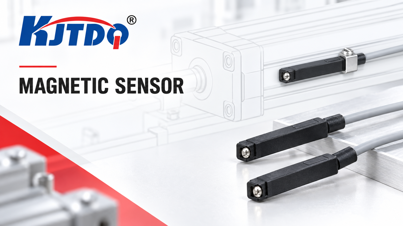
A cylinder magnetic sensor that switches twice on one piston pass is usually seeing a magnet-field structure with two actuation zones — the piston ring's field has leading and trailing edges, and a sensor positioned where both edges cross it produces two pulses — or it is responding to vibration/other magnetic fields near the trip point. A lost end signal usually means the sensor sits where the piston magnet's field is too weak (position error), the piston physically does not reach the sensing zone (stroke/cushioning issue), or the speed is too high for the input chain to register. The first safe check is positional: with the machine at rest, hand-move the piston (or jog per site procedure) and map exactly where the sensor switches along the stroke. All checks near moving machinery are stopped-machine work.
Key Takeaways
- A piston magnet has a field profile, not a point. The ring magnet produces a detectable zone with edges; where the sensor sits inside that zone determines single, double or lost switching. Position is the application.
- Double switching is classic edge-crossing. Both field edges crossing the sensor's hysteresis band produce two pulses per pass; moving the sensor fully inside (or outside) the zone — or selecting appropriate hysteresis — resolves it.
- Lost end signal is usually geometry. The sensor sits beyond the magnet's reach at full extension, the piston does not fully stroke (cushioning, mechanical stop), or the magnet has weakened — each has a distinct check.
- Speed interacts with the input chain. A fast piston can produce a shorter ON-time than the PLC input filter or scan accepts; the sensor switched — the logic missed it.
- Nearby magnetism and vibration fake both symptoms. Welding fixtures, adjacent cylinders' magnets and bracket vibration move the sensor's effective trip point; correlation with machine state identifies them.
Symptom / Likely Cause / Safe Check Table
| Symptom | Likely cause | Safe check |
|---|---|---|
| Two pulses per piston pass | Sensor positioned where both edges of the magnet zone cross the hysteresis band; hysteresis too narrow for the zone | Hand-cycle (machine at rest) and mark both switch points along the stroke; compare their separation with the sensor's zone behavior |
| End signal missing entirely | Sensor beyond the magnet's detectable zone at full stroke; piston not reaching full stroke; weakened/damaged magnet | Slowly hand-stroke the piston to full extension and watch the indicator; mark the switch zone vs. sensor position; verify piston reaches the mechanical end |
| Signal lost only at high speed | ON-time shorter than PLC input filter/scan accepts | Compare pulse duration at operating speed with the input filter/scan specification; observe indicator vs. PLC tag (indicator shows the switch the logic missed) |
| Chatter at the trip point | Vibration moving sensor or field across the threshold; nearby magnetic field | Correlate with machine vibration state; check for adjacent magnets (other cylinders, fixtures) within influence distance |
| Worked before, fails after service | Sensor re-mounted at a different position; different cylinder (different magnet); bracket change | Compare current mounting position against commissioning marks; verify cylinder model unchanged |
| Intermittent loss, worse with motion | Cable/connector flexing at the cylinder (the classic moving-point failure) | Inspect cable at the moving point for damage; wiggle-test by qualified personnel with logic monitored |
| Both end sensors behave oddly | External magnetic source or shared-path electrical fault | Map other magnetic sources near the cylinder; check both sensors' common path |
Safety Boundary
Safe observations: with the machine stopped and locked out, hand-stroking or jogging the piston per the site's procedure while watching the sensor indicator; marking switch positions; visual inspection of mounting, cable and cylinder.
Qualified-person work: any electrical verification (continuity, supply, wiggle-testing with power), PLC input configuration changes, and any work requiring the machine to move under power — those need the site's procedures and, where relevant, personnel clear of moving parts. Pneumatic systems store energy: follow lockout/vent procedures before touching the mechanism.
Inputs to Collect Before Changing Settings
- Cylinder brand and model, bore, stroke, and whether the piston magnet is confirmed (datasheet or previous operation);
- Sensor model and mounting type (groove / round-body tie-rod format / other per the installed type), with its hysteresis/switching-point behavior from the data sheet;
- Measured switch zone: where along the stroke the sensor switches and releases (hand-cycle marks);
- Operating piston speed and required signal duration in the logic;
- Nearby magnetic sources: adjacent cylinders, magnetic fixtures, welding equipment;
- PLC input filter/scan settings for the channel;
- Fault history: since when, after what change, at what speeds.
Diagnostic Sequence (Least Invasive to Specialized)
- Observation: double switching on each pass. Hypothesis: both edges of the magnet zone cross the sensor. Check: hand-cycle at rest; mark both switch points and the zone extent. Expected result: two distinct switch positions close together within the magnet zone. Next action: reposition the sensor fully inside the zone (or per the application's required signal point) so a single continuous ON results; verify at operating speed.
- Observation: end signal missing. Hypothesis: sensor outside the detectable zone at full stroke. Check: hand-stroke fully; note the furthest switch position vs. the sensor location. Expected result: the magnet's zone ends before the sensor position. Next action: move the sensor into the zone at the true end position; re-verify.
- Observation: end signal missing even with correct zone overlap. Hypothesis: piston does not reach full stroke (cushioning set too hard, mechanical stop, pressure low). Check: verify piston position at full extend against the mechanical end (visual/mechanical, machine locked out). Expected result: piston stops short of the zone. Next action: correct the pneumatic/mechanical cause — the sensor is honest.
- Observation: signal present at slow speed, absent at operating speed. Hypothesis: ON-time below the input chain's resolution. Check: estimate pulse duration from piston speed and zone length; compare with PLC input filter/scan. Expected result: duration shorter than the logic accepts. Next action: adjust input filter/scan within the logic design, or extend the detectable zone (position/sensor choice); the indicator-vs-PLC comparison confirms it (see the pulse-chain method in speed-sensor pulse troubleshooting guide).
- Observation: chatter or double-switching correlating with machine vibration. Hypothesis: vibration or external magnetic field near the trip point. Check: correlate with machine state; survey adjacent magnets (other cylinders, fixtures) within influence distance. Expected result: symptom appears only with the vibration source or specific adjacent cylinder active. Next action: stiffen mounting or move away from the external field; re-verify.
- Observation: intermittent faults with motion. Hypothesis: cable/connector flex failure at the moving point. Check: qualified-personnel wiggle test with logic monitored; inspect the cable at the flex point. Expected result: fault reproduced by specific cable positions. Next action: replace the cable/connector with the correct part (the replacement-equivalence discipline is in cable-or-bracket replacement topic).
- Observation: symptoms since a cylinder or sensor replacement. Hypothesis: different magnet strength/position (new cylinder) or different sensor model behavior. Check: compare cylinder and sensor models old vs. new against commissioning records. Expected result: a substitution explains the change. Next action: re-run steps 1–2 for the new hardware; the selection-side guidance is in magnetic-vs-inductive cylinder comparison.
- Observation: all checks pass, fault persists. Hypothesis: electrical path or input problem. Check: qualified personnel verify supply/output at the sensor and the input channel. Expected result: path fault isolated. Next action: route to the PLC input guide (intermittent-PLC-input troubleshooting guide).
Conditional Corrective Actions
- Double switching confirmed as edge-crossing → reposition the sensor inside the zone; if the application needs the signal exactly at an edge position, discuss a model with suitable hysteresis behavior with support.
- Piston not reaching the zone → fix the pneumatic/mechanical cause (cushioning, stops, pressure) — do not move the sensor to a "convenient" position that no longer confirms the end.
- Speed/pulse-width mismatch → correct the input chain (filter/scan) or zone length; never accept a "sometimes-missed" end signal in sequencing logic.
- External field influence → increase distance or reorient; verify adjacent-cylinder layouts in multi-cylinder stations.
- Flex-point cable failure → replace with the specified cable and restore strain relief per the machine design.
Replacement and Reselection Criteria
Reselect when: the cylinder's magnet/sensor combination cannot produce the required signal at the required position and speed; the environment demands a variant family (welding areas generate fields and spatter — welding-area versions exist; hazardous areas require the explosion-proof variant, selected against the area classification); or the mounting format does not fit the cylinder (the format matching — groove, tie-rod formats — is selection guidance in magnetic-vs-inductive cylinder comparison). For end-of-travel applications where magnetic sensing fundamentally cannot meet the requirement, the position/limit-detection alternatives are compared in magnetic-vs-inductive cylinder comparison and travel-detection comparison.
Information to Send KJT Sensors Support
- Cylinder brand/model, bore and stroke; piston-magnet confirmation;
- Sensor model and mounting type; mounting position photos with the switch-zone marks;
- Hand-cycle switch-zone measurement (switch point, release point, zone length);
- Operating piston speed and required logic behavior (minimum ON-time);
- Nearby magnetic sources description; vibration state correlation;
- PLC input filter/scan settings; fault history and what changed.
Limitations
- Switching point, hysteresis and zone behavior are model- and cylinder-specific: no numeric values are given; verify on the actual cylinder (KJT Sensors' magnetic sensors are stated to detect permanent magnets of all strengths on all common cylinder pistons — manufacturer-stated; the installed reality is verified on the machine).
- This article covers installed-sensor diagnosis; choosing magnetic vs. inductive for a new application is owned by C03 (magnetic-vs-inductive cylinder comparison).
Frequently Asked Questions
Why does a cylinder magnetic sensor switch twice?
Because the piston magnet's field forms a zone with two edges, and the sensor sits where both edges cross its hysteresis band — one switch on entry, one on exit, with a brief release between them. Hand-cycle the piston at rest, mark both switch points, and reposition the sensor so the pass produces one continuous signal. If the application genuinely needs a signal at the edge, the sensor's hysteresis behavior becomes the selection variable — discuss it with support.
Why is the cylinder end-position signal sometimes lost?
Three families: geometry (sensor beyond the magnet's zone, or the piston stopping short of full stroke — cushioning, stops, pressure), speed (ON-time shorter than the PLC input chain accepts — the indicator switches, the logic misses), and path (flexing cable at the moving point, connector faults). The hand-cycle map distinguishes geometry; the indicator-vs-PLC comparison distinguishes speed; the wiggle test distinguishes path.
How do sensor position and piston speed affect switching?
Position decides which part of the magnet zone the sensor sees — inside it, one continuous signal; straddling an edge, double switching; outside it, nothing. Speed decides how long the signal lasts: zone length divided by piston speed gives ON-time, which must exceed what the PLC input filter and scan can register. A slow hand-cycle proves the sensor; operating speed proves the chain — test both.
Conclusion
Map the magnet's switch zone by hand-cycle before theorizing: position fixes double switching and most lost signals; piston stroke and cushioning explain the rest of the geometry cases; speed and the input chain explain "sensor works, logic misses"; flex-point cables explain intermittence. Reposition, correct the mechanics, match the chain, and only then consider a different sensor — with the format and environment variants selected through C03's guidance.
Sources
- KJT Sensors, Magnetic Sensor category (groove, round-body tie-rod and related mounting formats; wear-free, short-circuit-proof, IP67; welding-area, explosion-proof and analog-output versions; detects permanent magnets of all strengths on all common cylinder pistons — manufacturer-stated; verified 2026-10-10) — https://www.kjt-sensors.com/list-cgycgq.html
- KJT Sensors, Service & Support — https://www.kjt-sensors.com/list-services.html (verified 2026-10-10)
- KJT Sensors internal knowledge base: magnetic and Hall-effect sensors (selection inputs: cylinder brand, groove type, magnet condition) — version current at drafting
- General pneumatic position-sensing practice (magnet zone behavior, hysteresis, cushioning effects; no third-party claims)
Send Cylinder and Sensor Details
Provide the cylinder model, sensor model and mounting type, the hand-cycle switch-zone measurement, and the operating speed with required logic behavior via the KJT Sensors service page — application engineers will verify the position/hysteresis logic or recommend the matching variant.
https://www.kjt-sensors.com/
KJT Sensors
About Author